
Home/Applications/ERV / HRV
OEM applications
Blowers for ERV, HRV and Fresh-Air Units
A heat recovery ventilator is two fans, one core, two filters and a cabinet. This page is about the two fans. LONGWELL has made fan and blower components in Yuyao, Ningbo since 1990 and ships to more than 30 countries. What we supply into ERV, HRV and fresh-air units is the motorised blower: impeller, external-rotor motor, scroll housing and, on EC and DC, the drive electronics. This site covers the blower rather than the finished ventilator: the core, cabinet, controller, defrost logic and drain stay on your side of the drawing.
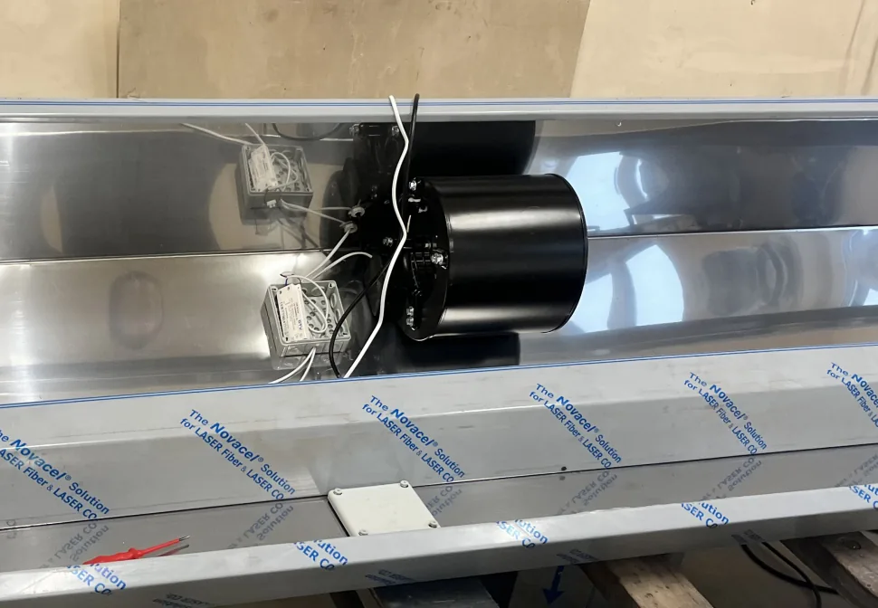
The two-fan problem: supply and extract have to stay balanced
Balance is a design condition, not a wiring condition. With a clean core and clean filters the two fans are easy to set to the same volume; what happens afterwards is the engineering problem. The airstreams do not load at the same rate. The supply side pulls outdoor air through the finer medium, a washable primary plus an F5 combined medium or an H12 or H13 panel on higher-specification units, and that gains pressure drop as it collects dust and pollen. The extract side runs a coarser filter but breathes kitchen aerosol, lint and bathroom moisture, and in some dwellings it blocks first.
Two fixed-speed motors cannot hold a ratio through that. A forward-curved blower on a fixed tap walks back along its own curve as resistance rises, and because that curve is comparatively flat through mid-range, 60 to 80 Pa of added filter resistance costs a large slice of flow. When one side loses more than the other the building ends up pressurised or depressurised, recovery efficiency falls because the exchange is limited by the smaller of the two mass flows, frost risk on the cold face rises, and a depressurised dwelling pulls outdoor air in through the fabric, where interstitial condensation starts. So size the pair at the dirty-filter end of its life, and check the clean condition too: a forward-curved impeller draws more power as resistance drops.
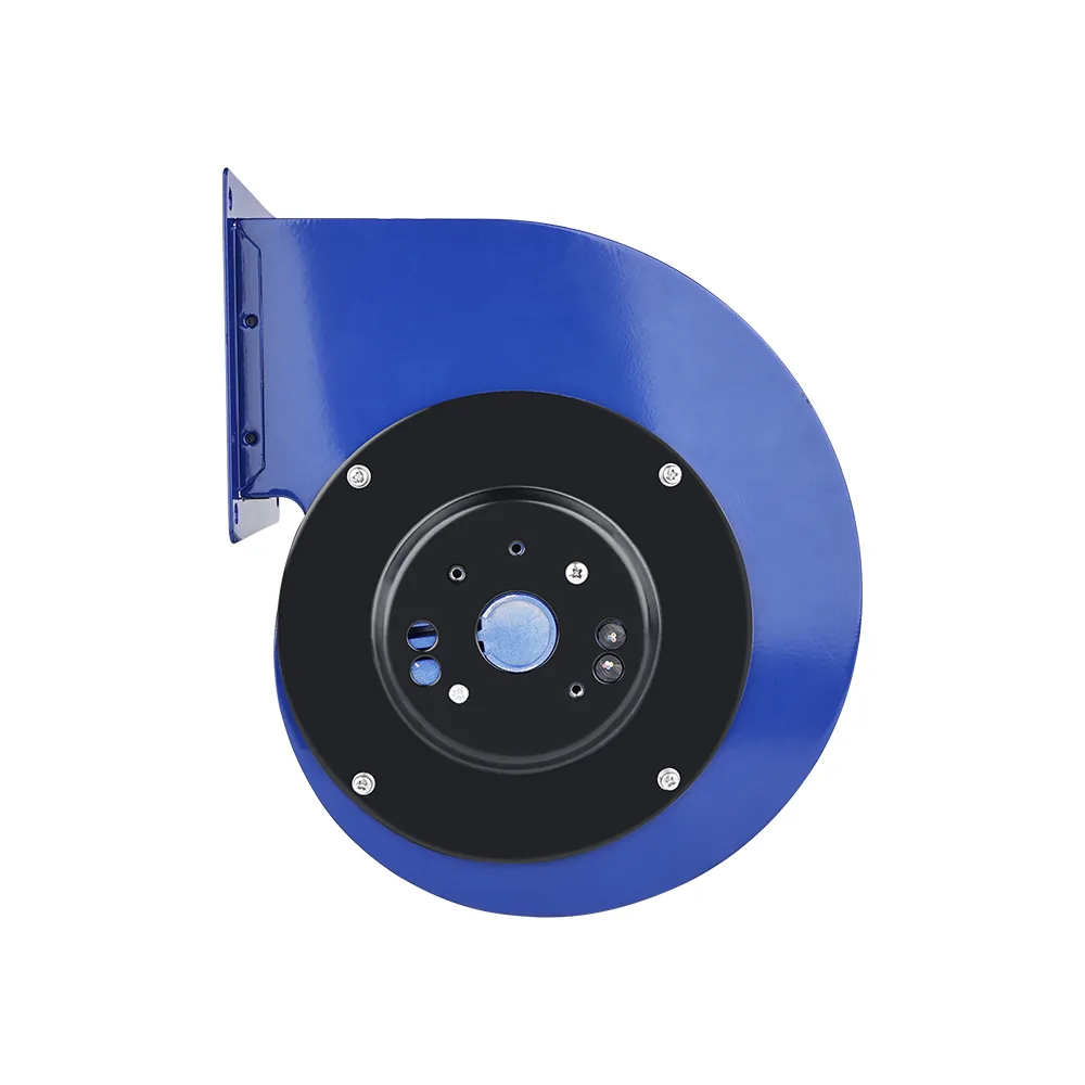
Why EC control earns its place in a recovery unit
An EC blower carries a permanent-magnet brushless motor with the drive board built in, so there is no separate inverter to mount, wire or take through your EMC file. That matters more in a two-fan machine, where the sides must be trimmed independently and re-trimmed over the unit's life.
- Step-less speed on each side. 0-10 V or PWM input as standard, PWM at 1 to 10 kHz on the 092-rotor units we checked. Supply and extract are set separately instead of matching taps and fitting balancing dampers.
- Speed feedback. An FG tacho output reports running speed; the 138-rotor unit we checked returns 12 pulses per revolution.
- Bus control where the model allows it. RS485 on the 102, 138 and 188 rotor sizes; rotor size is the second number in the model code, so the code tells you whether the option exists.
- Part-load energy. About 30% lower consumption at part load, confirmed against the load profile. A ventilator running continuously, mostly below boost speed, is where that is real.
One honest limit: our EC drives hold speed, not flow. Holding a constant volume as the filter loads means closing a loop, in your controller against a flow or differential-pressure sensor, or with a drive that carries the flow model. Say which at enquiry stage, so the right drive is quoted rather than assumed.
The pressure the core adds, and what that means for sizing
A plate core with roughly 3 mm plate spacing is a large share of the resistance the pair must overcome, in series with both filters, the ducting, the terminals and the weather hood. Across the residential and light-commercial recovery units we quote blowers into, rated duty runs roughly 150 to 2,000 m³/h per airstream with near 115 to 205 Pa available externally; single-direction fresh-air units without a core reach about 620 Pa at 2,000 m³/h. Deduct core and dirty filters before comparing a catalogue figure with your duty.
Four models from our EC and DC forward-curved ranges, as their specification sheets state them.
| Model | Build | Supply | Speed | Power | Max airflow | Max static | Noise |
|---|---|---|---|---|---|---|---|
| LWFE3G120-072SS-02 | EC, single inlet | 230 V, 176-264 V | 3,650 rpm | 75 W | 361 m³/h | 649 Pa | 61 dB(A) |
| LWFE3G133-092DS | EC, dual intake | 230 V, 176-264 V | 1,600 rpm | 90 W | 770 m³/h | 422 Pa | 64 dB(A) |
| LWFE3G146-092DS-02 | EC, dual intake | 230 V, 200-277 V | 1,450 rpm | 115 W | 1,009 m³/h | 670 Pa | 61 dB(A) |
| LWFD3G133-092DH-01 | DC 48 V build, two inlets | 48 V nominal (36-61 V per datasheet) | 1,750 rpm | 110 W | 773 m³/h | 294 Pa | 66 dB(A) |
Maximum airflow is free delivery and maximum static is closed outlet: two ends of a curve, never an operating point, so a blower is matched to a core on the curve itself. Behind those four sit 21 EC single inlet models, Ø120 to 250 mm at 42 to 510 W; 22 EC dual intake models, Ø120 to 355 mm, reaching 8,799 m³/h and 1,102 Pa; and 28 DC single inlet models at 24, 48 or 310 V. P-Q curves and CAD are on our selection site; range detail is on the EC centrifugal blower page and the DC brushless page.
Airflow, static pressure, voltage and control mode are enough for a first answer.
Condensation, dew point and temperature range
Catalogue ambient ratings reach +60 °C and go down to -20 °C on the 146 mm EC model, -25 °C on the 133 mm EC and the 48 V DC unit above. Check the minimum as carefully as the maximum: the supply blower sits in the cold path, and the defrost strategy will cold-soak, stop and restart it many times a winter.
An ambient rating is not a wet-airstream rating, and placement decides what each fan breathes. An extract fan downstream of the core in winter handles air that has given up its heat and is at or near saturation: droplets and running condensate, not just humidity. A supply fan downstream of the core gets the drier duty, and on an enthalpy core in a humid summer the wet side can swap. So four things belong on the drawing, not in an assumption: mounting orientation, whether the motor sits in the wet airstream, a drain path clear of the motor and terminal box, and whether the electronics are in the airstream at all.
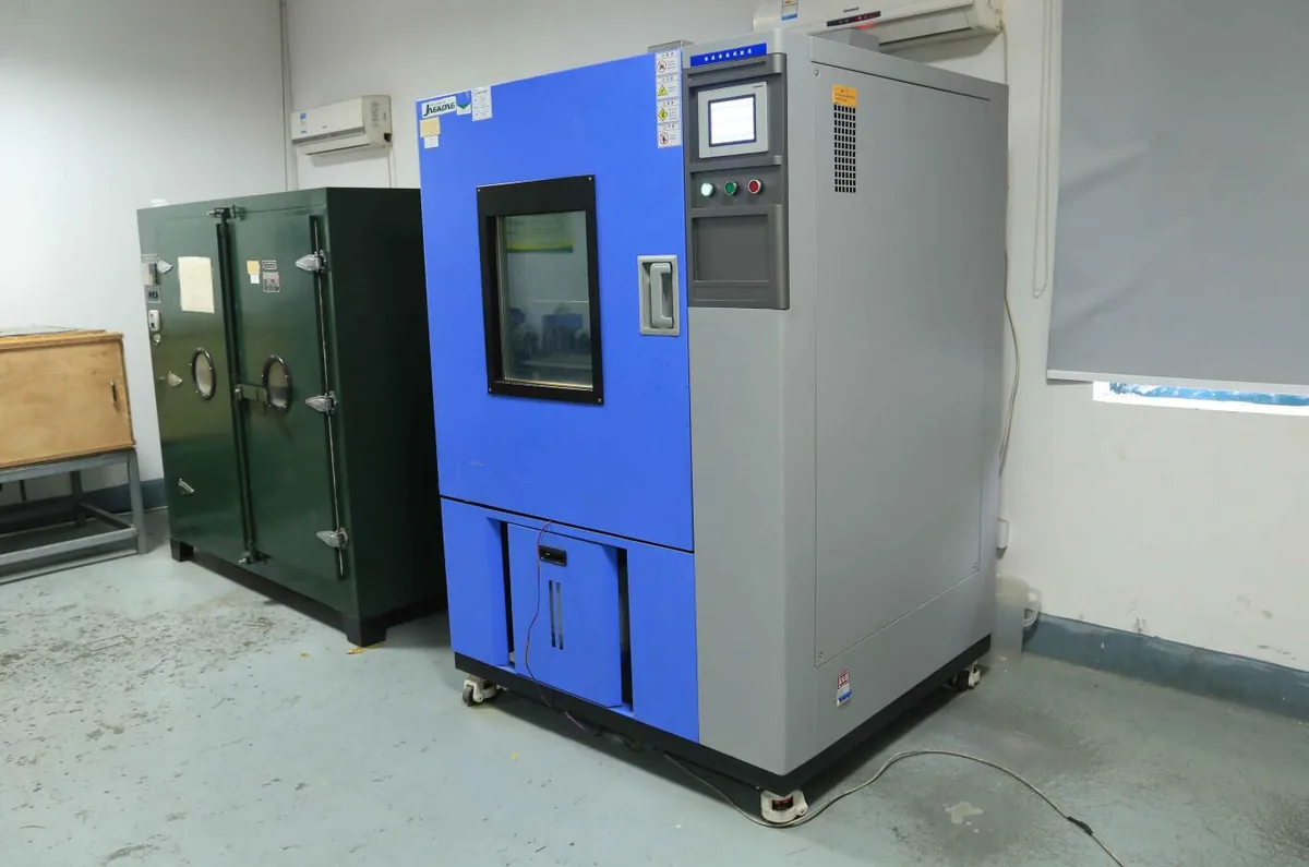
Motor protection in humid air
IP ratings here are catalogue design ratings, IP44 to IP54 by model, with class B or F insulation and S1 continuous duty; we hold no third-party IP certificate for them and do not claim one. An IP figure covers ingress from outside the motor, not moisture condensing on a winding inside a motor stopped in a saturated airstream. In humid duty the protections that count are the winding process, thermal and locked-rotor protection, bearing sealing, and running the fan long enough to dry it.
The motor winding line is one of two things we run in house, alongside cross-flow fan production: automatic winding and coil insertion, inter-turn insulation testing and argon-arc welding of the lead wires, audited in the 2021 ETL factory audit. The inter-turn test is the relevant one here, because it catches the marginal winding that survives a dry bench and fails in a saturated extract duct. Bearings are rated 20,000 h L10 at 70 °C on LWFE3G250-138DS-02 and impellers are balanced to G6.3, which matters for bearing life before noise. Everything other than motor winding and the cross-flow line is engineered and specified by LONGWELL, built to LONGWELL drawings in qualified partner plants and inspected to LONGWELL standards; wheel options are on our wheels and impellers page.
How an OEM specifies a pair
- Two duties, not one. Volume and external static for supply and extract at the dirty-filter condition, plus the clean condition for the power check.
- Which side each unit sits on, whether it runs wet, plus mounting orientation and drain path.
- Control and feedback. 0-10 V, PWM or RS485, where the constant-flow loop lives, and what the FG output drives.
- Supply. Single-phase mains, or 24 V, 48 V or 310 V DC on low-voltage units.
- Rotation, discharge orientation and noise limit. A pair often needs mirrored discharge in one cabinet, and catalogue dB(A) values are free-field: in-cabinet levels depend on your casing and lining.
- Certification scope. Our KTS CE certificates cover AC forward-curved LWFA108-450 only: LVD KB2207084L01, EMC KB2207085E01, RoHS KB2207086R01. ETL Recognized Component control number 5022563 covers part of the EC and DC range inside the report's model rule and power ceiling: about 1,100 W on EC, and 600 W at 48 V, 500 W at 24 V, 200 W at 12 V on DC. ISO 9001 BMCQ0222448M, 14001 BMCE0222279M and 45001 BMCS0222232M run to 2028-12-08. Air performance is tested to the AMCA 210 method; acoustic room calibration SSD202500326. More on quality and certifications.
- Programme. Samples in 1-3 days on catalogue models, production in 15-30 days, 12 months warranty. Drawing to first article follows our OEM process.
Send both duties, the core pressure drop and the filter classes, and we will come back with a pairing, curves and a drawing. Talk to our OEM team.
Questions buyers ask
Do you supply the complete ERV or HRV unit?
No. We supply the blower: impeller, external-rotor motor, scroll housing and, on EC and DC models, the drive electronics. The core, filters, cabinet, controller, defrost strategy and condensate drain stay with you. We also have no part numbers for ventilators already installed in buildings, so replacement enquiries need to go to the unit maker.
Can one model cover both the supply and the extract side?
Often yes, when both airstreams see a similar duty, and it simplifies your bill of materials. Two things usually stop it: the two sides may need mirrored discharge orientation inside one cabinet, and the wet side may need different mounting or drainage. With EC or DC control you can run the same model at two different speeds rather than buying two models.
Do your EC blowers hold constant airflow as the filters load?
The drive holds speed, not flow. Constant volume means closing a loop either in your unit controller against a flow or differential-pressure sensor, or with a drive that carries the flow model itself. Tell us which you need at enquiry stage so the right drive is quoted rather than assumed; the blower side gives you 0-10 V or PWM input, an FG tacho output and, on the 102, 138 and 188 rotor sizes, RS485.
What temperature range can these blowers work over?
Catalogue ambient ratings reach +60 degrees C, with minimums of -20 degrees C on the 146 mm EC model and -25 degrees C on the 133 mm EC and the 48 V DC model. In a recovery unit the minimum usually matters more than the maximum, because the supply blower sits in the cold path and gets cold-soaked, stopped and restarted through the defrost cycle.
Is the air performance data AMCA certified?
No. Air performance is tested to the AMCA 210 method on our own rig, and our acoustic room calibration is SSD202500326. On product certification, the KTS CE certificates cover AC forward-curved models LWFA108-450 only, and ETL Recognized Component control number 5022563 covers part of the EC and DC range within the report's model rule and power ceiling. We state the scope rather than implying blanket coverage.
What are the lead times for a sample and for production?
Samples of catalogue models in 1-3 days, production in 15-30 days, and 12 months warranty. Non-catalogue builds, such as a special housing orientation or a drawing-specific wheel and motor pairing, run through our OEM process with a first article before series release.
Where to go next
Air Purifier Blowers for HEPA and Clean-Air Equipment
Sizing, noise, 0-10 V and PWM control, mounting and safety for air purifier blowers. EC and DC forward-curved volute blowers from a China OEM blower maker.
Read the pageCentrifugal Air Blowers – Scroll and Volute Blower Range
LONGWELL scroll (volute) centrifugal air blowers: AC, EC, DC and gas lines, 77–355 mm, to 8,799 m³/h and 4,100 Pa. Compare the five lines.
Read the pageBlower Factory and OEM Manufacturing Capability
What LONGWELL builds in its own Yuyao plant, what partner plants build to our drawings, and the drawing, balancing and test controls an auditor can check.
Read the pageQuality and Certifications
Every certificate we hold, with numbers and scope: ISO 9001/14001/45001, KTS CE for LWFA108-450, ETL Recognized Component 5022563, AMCA 210 method testing.
Read the pageSend the duty point, get the model
Airflow, static pressure, voltage and control mode are enough to start — a drawing is better. An engineer answers, usually within one working day (GMT+8). Samples of catalogue models ship in 1–3 days.